Boiler burners structure and working principle
A burner is a general term for devices that allow fuel and air to be sprayed and mixed (or mixed and sprayed) to burn in a certain way. According to its working principle, a burner can be defined as a kind of equipment that converts substances into heat energy through the chemical reaction of burning—that is, air and fuel are mixed in proper proportions through a premixing device to make them fully combustible. We don’t know much about it. The editor of Boiler.com in this issue brings the structure and working principle of the boiler burner, and attaches the structure diagram and assembly parts of the boiler burner!


A: Boiler burner structure and working principle
1. After the control power of the burner is turned on, the air pressure is first detected, and the corresponding corresponding pressure switch is high pressure and pressure switch low pressure. Controller for short) can be formally powered on.
2. After the controller is energized and the operation command is obtained (the combustion permission switch is turned on), the leak detector starts to work and detects the pressure of the valve group in sequence.
First, the air valve 5 is opened to release the pressure. After the pressure is released, the pressure switch must be lower than the low set value, and the air valve 5 is closed again. After that, the air valve 4 is opened and the pressure switch is detected. The pressure switch must be in the pressure position, and then the air valve 4 Closed again, the valve group enters the pressure maintaining state.
The pressure within the specified time of the leak detector shall not be lower than the maximum return difference value of the pressure switch. During this process, when the pressure detection switch is not in the corresponding position, the leak detector will send out an alarm chain signal.
3. After the leak detection is passed, the burner program controller is in normal working state, and the pre-purge is started.
4. After the pre-purge is finished, the servo motor runs to the ignition load position, the valve (4) and valve (7) are opened, and after the flame is formed in the gas nozzle (11), the valve (5) is opened, and the gas flows to the nozzle to be ignited. The flame burns under the ignition load. When no flame is detected or no ignition is detected, the flame reaction is abnormal, and an alarm interlock signal will be issued.
5. The load controller controls the servo motor. It adjusts the gas butterfly valve and damper control rod between partial load and full load according to the load requirements. The adjustment is controlled by increasing the load and decreasing the load.
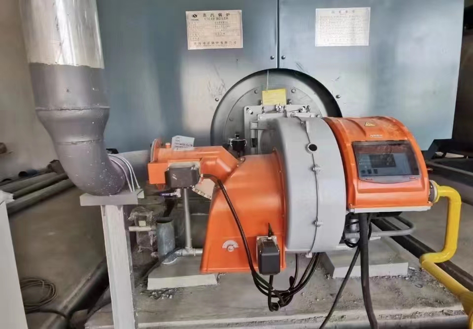
B: Boiler burner structure diagram and assembly parts
It mainly consists of the following 5 systems:
1. Air supply system: The function of the air supply system is to send air with a certain wind speed and volume into the combustion chamber.
Its main components are: casing, fan motor, fan impeller, fan fire pipe, damper controller, damper baffle, cam adjustment mechanism, and diffusion disc.
2. Ignition system: The function of the ignition system of the furnace burner is to ignite the mixture of air and fuel.
Its main components are: ignition transformer, ignition electrode, electric fire high voltage cable.
3. Monitoring system: The function of the monitoring system is to ensure the safe and stable operation of the burner.
Its main components include flame monitor, pressure monitor, temperature monitor, etc.
4. Fuel system: The function of the fuel system of the heating furnace burner is to ensure the fuel required for the burner to burn.
The fuel system of the oil burner mainly includes: oil pipes and joints, oil pumps, solenoid valves, nozzles, and heavy oil preheaters. Gas burners mainly include filters, pressure regulators, solenoid valves, ignition solenoid valves, and fuel butterfly valves.
5. Electronic control system: The electronic control system is the command center and contact center of the above systems. The main control element is the program controller, which is equipped with different program controllers for different sulfur recovery burners.
The common program controllers are: LFL series, LAL series, LOA series, LGB series, the main difference is that the time of each program step is different.